Modulated IR Sensor
This software is designed to work with the very inexpensive four way infrared sensors as found in prolific quantities on Amazon, AliExpress, and eBay, and allow these to be integrated with DCC-EX EX-CommandStation via the EX-IOExpander device driver.
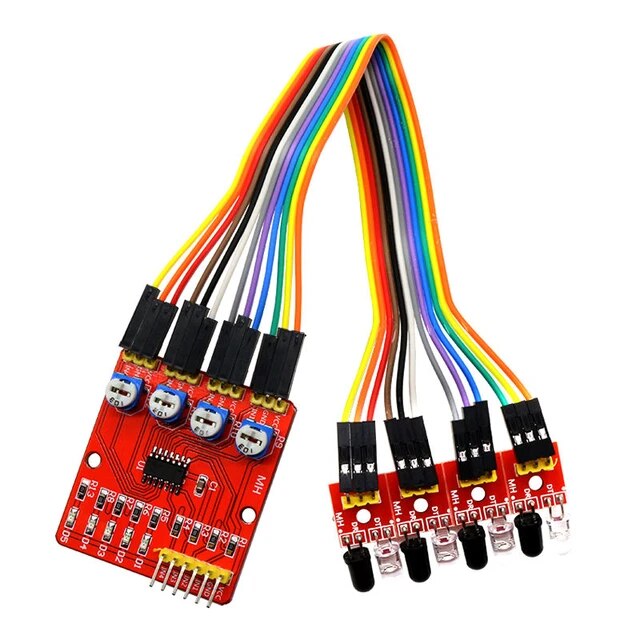
These sensors are dirt cheap, but given they are very simply designed become somewhat unreliable and unpredictable in various types of (un)natural lighting. This software was written to work with components I had on hand to provide what is essentially a software-only solution to making them more reliable.
This software is available in my ModulatedIRSensor GitHub repository.
While both the Arduino Mega and STM32F103C8 Bluepill will work with this software and the sensors and have been tested, there should be nothing microcontroller specific aside from the defined pin names.
Theory of operation
As-is hardware operation
With the out-of-the-box sensors, these are configured in reflection mode, and an object must be close enough to reflect the IR beam from the trasmitter back to the receiver in order to activate it. The output pin should be HIGH when there is no reflected IR beam from the trasmitter, and only transition to LOW when an object causes a reflection to activate it.
It is also possible to desolder the IR LED and have it facing the receiver (remember you’ll still need a current limiting resistor), changing the setup to be in beam break mode. In this mode, the output pin should be LOW as it will always be receiving the IR beam, and therefore will always be activated. When an object passes between the IR LED and receiver and blocks the beam, it should set the output pin HIGH as it is deactivated.
Note that with this software, the larger PCB is no longer required, and only the individual sensor PCBs are required.
Software operation
The idea of making these sensors more reliable is a fairly simple concept of a square wave being transmitted via the IR LED and checking the receiver to ensure it is responding appropriately, with the receiver state being captured in a rolling window to ensure the state is consistent with the transmitter for a continuous 10 cycles. The transmitter is alternated between HIGH and LOW states every 10,000 microseconds by default (this value is customisable).
In the case of the default reflection mode, when there is no object close enough to reflect the beam, the output pin should continuously be HIGH (sensor continuously deactivated).
When an object is close enough to reflect the beam, the output pin should alternate between HIGH (deactivated) when the IR LED is off, and LOW (activated) when the IR LED is on.
This activity is captured in a rolling window of 10 samples and only when all 10 samples are consistent between the transmitter and receiver does the software consider the sensor activated.
Conversely, in beam break mode, the output pin should alternate between HIGH when the IR LED is off and low when the IR LED is on when there is no object between the transmitter and receiver.
When an object interrupts the beam, the output pin should always be HIGH, no matter whether the IR LED is on or off.
In beam break mode, the sensor is considered activated when the receiver is consistenly high over the 10 samples.
Sensor hardware modification
In order to control the state of the IR LED, the anode must be desoldered from the PCB, and connected to the appropriate pin of the microcontroller via a 150ohm current limiting resistor.
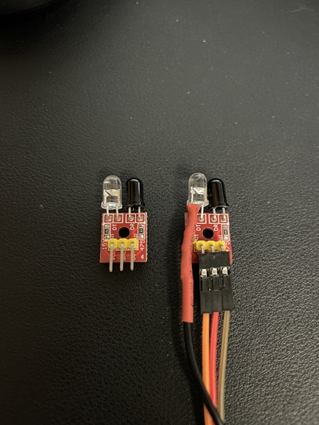
Note that with the Arduino Mega being 5v vs. the Bluepill’s 3.3V, the range of sensing is a lot higher with the standard 150 ohm current limiting resistor, and you may wish to consider a higher value if the sensors are triggered by objects further away than desired.
Once the sensor is modified, the IR LED’s anode is connected to the defined transmit pin on the Bluepill or Mega, and the PCB’s OUT pin is connected to the defined receive pin.
VCC and GND are connected to 5V/3.3V and ground pins respectively.
Using generic 3mm IR LEDs and IR receivers
As an alternative to purchasing and modifying these AliExpress type sensor boards, it is also possible to purchase generic bare 3mm IR LED/receiver pairs from places like eBay and use these instead.
These will still require a current limiting resistor for the IR LED, and a pullup resistor for the IR receiver, and you will need to design a way to mount them appropriately so they maintain appropriate alignment in reflection or beam break modes.
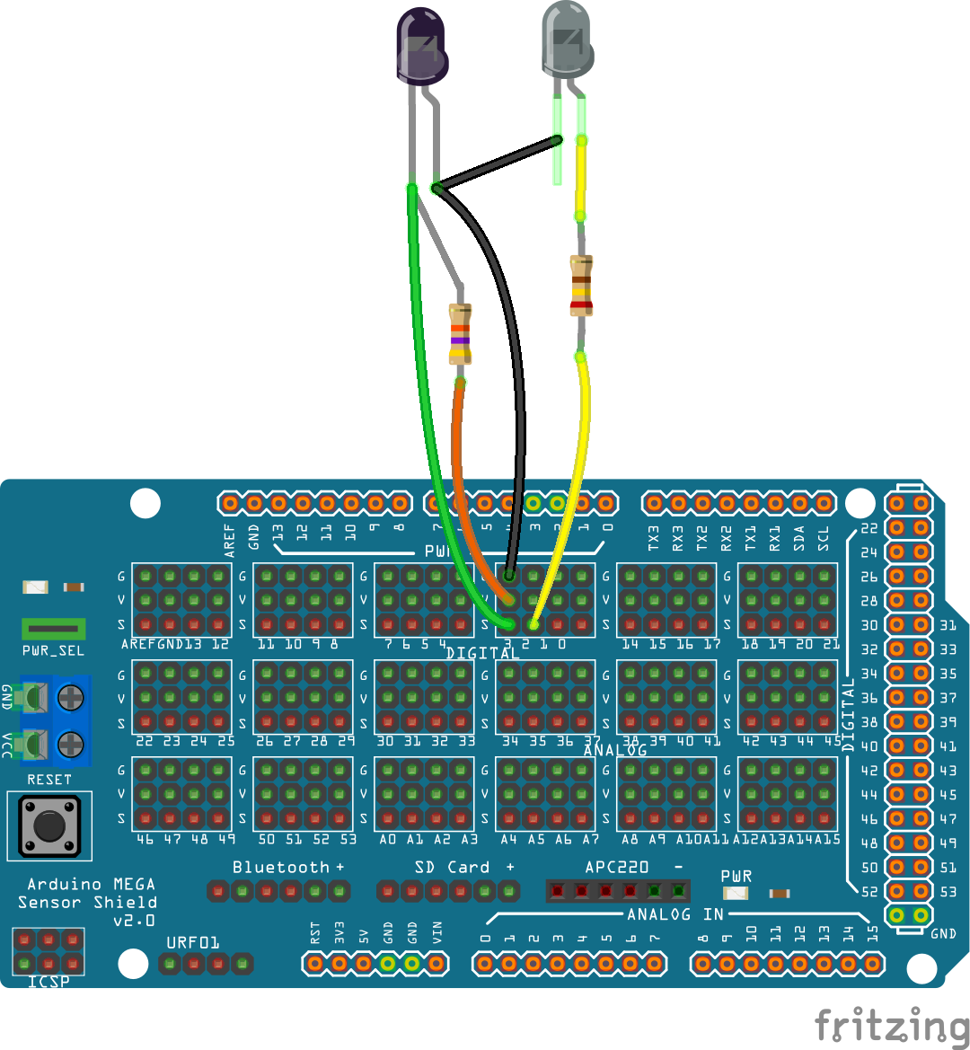
My experimentation revealed a 240ohm current limiting resistor for the IR LED and 10Kohm pullup resistor for the IR receiver yielded good, reliable detection at about a 20mm range.
Note when connecting the LEDs, that the IR LED is connecting in the normal, forward direction of anode (typically the longer leg) to the Arduino GPIO pin, and cathode (typically the shorter leg) to ground.
The IR receiver, however, is connected in reverse, with the anode (typically the longer leg) connected to ground, and the cathode (typically the shorter leg) connected to the Arduino GPIO pin along with the pullup resistor.
Sensor configuration
The IRSensor class is used to define each sensor object, which consists of a transmit and receive pin, along with various parameters that define the behaviour of the sensor:
IRSensor(int txPin, int rxPin, bool startState=true, bool beamBreak=false, bool activeHigh=false, unsigned long transmitDelay=20000, unsigned long responseDelay=20);
txPin - The pin the anode of the IR LED is connected to
rxPin - The pin the OUT pin of the sensor PCB is connected to
startState - The state that the IR LED starts in (default true)
beamBreak - Set true to enable beam break mode, otherwise the default reflection mode is in use (default false)
activeHigh - If for some reason the sensor in use is active high rather than active low, set this true (default false)
transmitDelay - The time in microseconds between inverting the IR LED state (default 20000)
responseDelay - The time in microseconds between changing the IR LED state and checking the receiver (default 20)
Some notes on these parameters:
It is recommended to alternate startState for each sensor to effectively halve the load of driving the IR LEDs from the microcontroller, and this has the added benefit whereby if one sensor is too close to another with the opposite startState, it will not incorrectly trigger
Testing indicated a transmitDelay of less than 10,000 uS caused issues, assumedly due to the time it takes the receiver to respond to state changes
Testing also indicated the receivers can be slower to respond when running at 5V vs. 3.3V, hence on the Mega the responseDelay was increased to 100 uS
Default pin definitions are provided for both the Arduino Mega (31 sensors) and STM32F103C8 Bluepill (14 sensors) as follows (note that Sensor ID is incremented automatically):
Sensor ID |
Tx Pin |
Rx Pin |
Start State |
Beam Break |
Active High |
Tx Delay |
Rx Delay |
|---|---|---|---|---|---|---|---|
0 |
2 |
3 |
true |
false |
false |
20000 |
100 |
1 |
4 |
5 |
false |
false |
false |
20000 |
100 |
2 |
6 |
7 |
true |
false |
false |
20000 |
100 |
3 |
8 |
9 |
false |
false |
false |
20000 |
100 |
4 |
10 |
11 |
true |
false |
false |
20000 |
100 |
5 |
12 |
13 |
false |
false |
false |
20000 |
100 |
6 |
14 |
15 |
true |
false |
false |
20000 |
100 |
7 |
16 |
17 |
false |
false |
false |
20000 |
100 |
8 |
18 |
19 |
true |
false |
false |
20000 |
100 |
9 |
22 |
23 |
false |
false |
false |
20000 |
100 |
10 |
24 |
25 |
true |
false |
false |
20000 |
100 |
11 |
26 |
27 |
false |
false |
false |
20000 |
100 |
12 |
28 |
29 |
true |
false |
false |
20000 |
100 |
13 |
30 |
31 |
false |
false |
false |
20000 |
100 |
14 |
32 |
33 |
true |
false |
false |
20000 |
100 |
15 |
34 |
35 |
false |
false |
false |
20000 |
100 |
16 |
36 |
37 |
true |
false |
false |
20000 |
100 |
17 |
38 |
39 |
false |
false |
false |
20000 |
100 |
18 |
40 |
41 |
true |
false |
false |
20000 |
100 |
19 |
42 |
43 |
false |
false |
false |
20000 |
100 |
20 |
44 |
45 |
true |
false |
false |
20000 |
100 |
21 |
46 |
47 |
false |
false |
false |
20000 |
100 |
22 |
48 |
49 |
true |
false |
false |
20000 |
100 |
23 |
A0 |
A1 |
false |
false |
false |
20000 |
100 |
24 |
A2 |
A3 |
true |
false |
false |
20000 |
100 |
25 |
A4 |
A5 |
false |
false |
false |
20000 |
100 |
26 |
A6 |
A7 |
true |
false |
false |
20000 |
100 |
27 |
A8 |
A9 |
false |
false |
false |
20000 |
100 |
28 |
A10 |
A11 |
true |
false |
false |
20000 |
100 |
29 |
A12 |
A13 |
false |
false |
false |
20000 |
100 |
30 |
A14 |
A15 |
true |
false |
false |
20000 |
100 |
Sensor ID |
Tx Pin |
Rx Pin |
Start State |
|---|---|---|---|
0 |
PC13 |
PC14 |
true |
1 |
PC15 |
PA0 |
false |
2 |
PA1 |
PA2 |
true |
3 |
PA3 |
PA4 |
false |
4 |
PA5 |
PA6 |
true |
5 |
PA7 |
PB0 |
false |
6 |
PB1 |
PB10 |
true |
7 |
PB11 |
PB9 |
false |
8 |
PB8 |
PB5 |
true |
9 |
PB4 |
PB3 |
false |
10 |
PA15 |
PA10 |
true |
11 |
PA9 |
PA8 |
false |
12 |
PB15 |
PB14 |
true |
13 |
PB13 |
PB12 |
false |
User configuration
General options
There are only two options to configure:
I2C_ADDRESS - define the I2C address to use, default is 0x65
DIAG_CONFIG_DELAY - define the default diagnostic output delay in seconds, default is 5
To define a user configuration, copy the file “DefaultConfig.h” to “MyConfig.h” (note this is case sensitive), and update these values as required. Do not edit any other lines, although you can get rid of the copyright/license text if desired. The resultant file should look like this:
#ifndef MYCONFIG_H
#define MYCONFIG_H

#define I2C_ADDRESS 0x65
#define DIAG_CONFIG_DELAY 5

#endif
Sensor options
It is possible to enable user configuration of sensors on both the Bluepill and Mega by creating both a “MySensors.h” header file, and “MySensors.cpp” implementation file.
To enable a user configuration, you must create both of these files (noting the names are case sensitive) with the contents as show below, which contain an example using the first two default Bluepill sensor setups with all options explicitly defined.
“MySensors.h”
#ifndef MYSENSORS_H
#define MYSENSORS_H

// This is the number of user sensors to define
#define SENSOR_COUNT 2

#endif
“MySensors.cpp”
#include <Arduino.h>
#include "DeviceFunctions.h"

// Leave this line as is
IRSensor* sensors[SENSOR_COUNT]={
// Define each sensor in this format:
// new IRSensor(txPin,rxPin,startState,beamBreak,activeHigh,transmitDelay,responseDelay),
// There must be the same number of lines defined here to match SENSOR_COUNT in MySensors.h
  new IRSensor(PC13,PC14,true,false,false,20000,20),
  new IRSensor(PC15,PA0,false,false,false,20000,20),
};
Adjusting range
If the range of the sensors using the default values outlined here don’t suit your needs, then the current limiting resistor for the IR LED can be changed (lower value resistor, longer range), and adjusting the responseDelay value tends to also impact the range.
Be very careful with the current limiting resistor though, as the Arduino device GPIO pins can only source a limited amount of current, so reducing this value too much will likely lead to damaging the GPIO pins of the device when exceeding their current limits.
Adjusting the responseDelay value is the preferred starting point as a result, and decreasing this will typically reduce the range, and increasing it may increase the range, although the default of 100ms on the Mega is likely the maximum range on that platform.
EX-CommandStation integration
If desired, this software can integrate with EX-CommandStation via the EX-IOExpander device driver when connected to the I2C bus.
I highly recommend familiarising yourself with the EX-IOExpander documentation linked above as I will not cover any of that here, and will focus only on the specific configuration required for this software.
To enable this integration, you simply need to add the appropriate HAL(EXIOExpander,vpin,sensors,I2C address) line to “myAutomation.h”, whereby:
vpin - The first Vpin at which your sensors will start being numbered
sensors - The number of sensors defined either in “MySensors.h” or the default Bluepill (14) or Mega (31) options
I2C address - The I2C address defined in “MyConfig.h” or the default 0x65
Example “myAutomation.h” for the example above using “MySensors.h” and “MySensors.cpp” at the default I2C address:
HAL(EXIOExpander,800,2,0x65)
Interactive commands
A subset of the EX-IOExpander commands have been implemented in this software:
<D> - Enable/disable diagnostic output, which displays at the intervals defined by the DIAG_CONFIG_DELAY setting
<D x> - Change the display interval, where x is the number of seconds in whole numbers
<V> - Display the mapping of Vpins to physical sensor configuation
<Z> - Reboot