Control Knob Mode
In the control knob mode, an OLED displays both the last position sent to the EX-CommandStation in addition to the currently selected rotary encoder position.
A single button press will send the current rotary encoder position to the EX-CommandStation.
Valid positions are from -127 to 127, as a single byte is used to send this value over I2C, with rotation in a clockwise direction incrementing from 0 to 127, and counter-clockwise decrementing to -127. The direction can be reversed via configuration option.
Hardware details

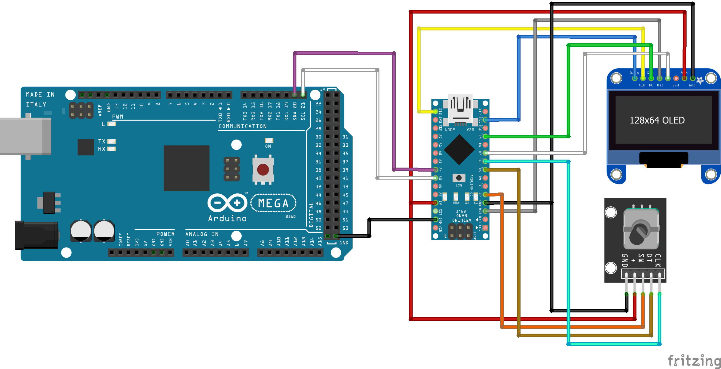
A suitable rotary encoder (tested on KY-040) and SPI OLED connected to a suitable AVR based Arduino (tested on a Nano) is all that’s required for the generic control knob functionality, with the Arduino connected to your EX-CommandStation via I2C as outlined in the Fritzing diagram.
Configuration options
Various configuration options can be edited in the file “config.h”. By default, this file does not exist, and an example file “config.example.h” with the various options has been provided. It is recommended to copy the example file to your own “config.h”, as the example file will be overwritten by any future changes to the software.
For general configuration options, refer to General configuration options.
Knob mode configuration options
The only configuration options required in control knob mode are for the OLED connections.
Option |
Default |
Details and options |
|---|---|---|
OLED_CS |
7 |
OLED CS/chip select pin |
OLED_DC |
9 |
OLED DC pin |
/////////////////////////////////////////////////////////////////////////////////////
//  START: KNOB mode configuration options.
/////////////////////////////////////////////////////////////////////////////////////
#define OLED_CS  7        // Define OLED CS/chip select pin
#define OLED_DC  9        // Define OLED DC pin
/////////////////////////////////////////////////////////////////////////////////////
//  END: KNOB mode configuration options.
/////////////////////////////////////////////////////////////////////////////////////